
Precast, prestressed hollow-core slabs have been reliable and frequently chosen construction components for over fifty years. Designers, contractors, and owners appreciate their high-performance benefits such as year-round construction, fast-track site erection, low maintenance, and long-term durability, making them a preferred choice for floor and roof construction in hotels, apartments, schools, prisons, and a multitude of commercial building applications. Machine casting of hollow-core slabs provides high quality, mass production, and value pricing.
NiCore™ Planks from Nitterhouse Concrete Products, Inc. (NCP) perform an important structural role in combination with other structural components such as…
- Precast concrete column, beam, and wall framing
- Cast-In-Place concrete column, beam, and wall framing
- Concrete masonry walls
- Structural steel column and beam framing
- Cold-formed, steel stud wall framing
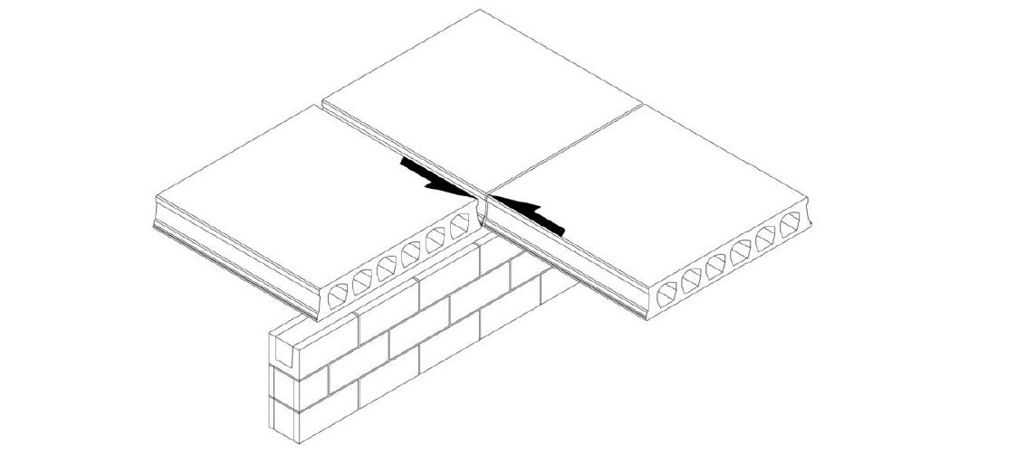
to complete the building structure. While connection details between these differing components do vary, one thing they all have in common is the longitudinal grouted joint between adjacent planks. These are sometimes also referred to as grout keys, and it is the purpose of this paper to address their design and construction features.
A very basic aspect of the longitudinal grout joints is their simplicity, but simplicity must not be equated with unimportance or irrelevance. They are generally classified as “wet connections” because they are constructed without the use of embedded hardware or expensive field welding. The sketch below depicts the appearance of these connections whereby the profile of the NiCore™ Plank has a longitudinal key configuration along its sides.
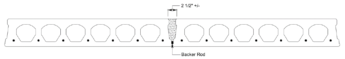
After the NiCore™ Plank are erected they are “leveled”, a term applied to the process of vertically aligning them within the PCI recommended tolerances by jacking from the surface below, or other means-and-methods chosen by the precast erector. After the “leveling” is completed, closed-cell, polyurethane foam backer rods are also inserted into the bottoms of the longitudinal joints. These simply serve as dams to contain the wet grout from seeping through to below. This is followed by placement of the loose reinforcing bars designed by the Engineer-Of-Record that are installed in the longitudinal grout joints, butt joints, side pockets, etc. These spaces are then grouted with a typical mixture having sufficient consistency so that end core dams are not required, and achieving a minimum 28-day compressive strength of 3,500 psi (Note: Grout strengths of 2,500 psi to 3,000 psi are also commonly acceptable and rarely cause for rejection). Typically, the grout mix is a ratio of 1-part cement to 2½ to 3 parts sand, by volume, with minimum water required for placement and hydration. The Portland cement shall comply with ASTM C 150, Type I, and used along with clean, natural sand complying with either ASTM C 144 or ASTM C 404. The water-soluble chloride ion content of the grout shall be less than 0.06% chloride ion by weight of cement.
The grout is delivered via redi-mix trucks to the job site, pumped, and placed into the joints. Up to about 20,000 s.f. of 8” NiCore™ Plank can be grouted in a single day. Very small jobs requiring ≤ 2 c.y. of grout are normally hand-mixed at the job site. Non-shrink grout and epoxy grout are not required for satisfactory performance of hollow-core slab systems. Not only do they command a premium cost, but they must be entirely mixed and placed by hand, resulting in a time-consuming and labor-intensive operation without adding any real value to the completed structure. Epoxy grouts might not be applicable where a fire-resistance rating is required, and their rate of thermal expansion can be seven (7) times that of conventional sand-cement grouts.
Longitudinal grout joints in NiCore™ Plank enable the individual precast units to somewhat emulate monolithic concrete behavior of the floors and roofs. They quietly perform multiple tasks throughout the life of the structure, and usually go unnoticed after the building is enclosed and the finishes applied. Those tasks include…
- Fire protection at the joints
- Transfer of vertical out-of-plane shear through the joints to permit load-sharing with adjacent units (ex: a heavy load on an individual NiCore™ Plank supported by multiple planks)
- Transfer of horizontal in-plane shear in the diaphragm through the joints and eventually to the lateral load-resisting elements such as shear walls, braced frames, moment frames, etc.
It is the latter of these tasks that we will consider now. While friction alone is considered insufficient for reliably resisting the loads for which a structure is designed, shear friction is a frequent structural component of connection design, and the longitudinal grout joints in NiCore™ Plank are fine examples. Diaphragms must have the strength to transfer imposed lateral forces such as wind and seismic loads from the diaphragms to the lateral load resisting elements. The diaphragms span between those elements and behave much like deep beams or tied arches, and the tensile and compressive stresses due to flexure and shear must be resisted within the diaphragms. The design shear strength of longitudinally grouted joints is 80 psi, and the factored shear capacity is represented by the equation:
ɸVn = ɸ(80 psi)(hnet)(Ljoint)
Conservatively assuming the grout depth is about 75% of the depth of the NiCore™ Plank, and ɸ = 0.75 as the strength reduction factor for shear, the factored shear capacity of the longitudinal joint for various plank thicknesses is…
- 6” NiCore™ Plank (ɸVn) = (0.75)(80 psi)(0.75)(6.0”)(12.0”) = 3,240 plf
- 8” NiCore™ Plank (ɸVn) = (0.75)(80 psi)(0.75)(8.0”)(12.0”) = 4,320 plf
- 10” NiCore™ Plank (ɸVn) = (0.75)(80 psi)(0.75)(10.0”)(12.0”) = 5,400 plf
- 12” NiCore™ Plank (ɸVn) = (0.75)(80 psi)(0.75)(12.0”)(12.0”) = 6,480 plf
- 16” NiCore™ Plank (ɸVn) = (0.75)(80 psi)(0.75)(16.0”)(12.0”) = 8,640 plf
The in-plane shear strength of the NiCore™ Plank also needs to be checked to determine whether it is less than the grouted longitudinal joints. For example, just about 6” away from the joint is the center of the first plank cell, where the in-plane shear demand is only resisted by the combined thicknesses of the top and bottom flanges. ttop = 1.5625” and tbottom = 1.375”, for tcombined = 2.9375”. The minimum 28-day concrete compressive strength of the NiCore™ Plank is 6,000 psi, and the factored shear capacity is represented by the equation:
ɸVn = ɸ(2)(f’c)0.5(tcombined)(Ljoint)
ɸVn = (0.75)(2)(6,000)0.5(2.9375”)(12.0”) = 4,100 plf
By inspection, the in-plane diaphragm shear strength for 6” NiCore™ Plank = 3,240 plf as controlled by the longitudinal grout joint, and that of all other NiCore™ Plank thicknesses = 4,100 plf as controlled by the NiCore™ Plank flange thicknesses.
In the unlikely chance that the strength of the longitudinal grout joint is exceeded there are obviously greater issues to be considered when evaluating in-plane diaphragm shears. However, to continue with the concept of shear friction, when the grout strength is exceeded or ductile behavior is desired, reinforcement is placed perpendicular to the longitudinal joints. This reinforcement should be placed in the transverse joints at the plank ends whenever possible rather than being distributed along the length of the joints. The area of steel is calculated as:
Avf = Vu / φfyμ
where,
μ = 1.0 for the coefficient of friction for shear parallel to longitudinal joints
φ = 0.75 for the strength reduction factor for shear
Example 1: Assume an 8” NiCore™ Plank spanning 30.0’. The amount of shear friction reinforcement needed to resist the in-plane shear is calculated as follows…
Avf = (4,100 plf)(30.0’) / (0.75)(60,000 psi)(1.0) = 2.73 in2 = 1.37 in2 per end [i.e.: 3 #7 bars]
This is a rather excessive amount of shear friction reinforcement based upon the in-plane diaphragm capacity of the 8” NiCore™ Plank. But, just how realistic is this example? What is a more realistic diaphragm shear?
Example 2: Assume a five (5) story hotel in Newark, NJ having a footprint of 60’ x 150’, 10’ story heights, and shear walls located at 30’ o.c. Assume intermediate reinforced masonry shear walls. Assume a total building dead load of 150 psf per level.
A preliminary seismic analysis yields a total base shear of about 492 K and a maximum story shear of 164 K at the roof level. Allowing for a 5% accidental torsion and assuming flexible diaphragms.
The shear at each wall ≈ (1.05)(164 K)(30.0’/150.0’) or 34.44 K.
The unit shear in the longitudinal grout joint ≈ 34,440# / 60.0’ ≈ 574 plf. It should be noted this is considerably less that the capacities of both the longitudinal grout joints and the 8” NiCore™ Plank itself.
Assuming again the length of the 8” NiCore™ Plank is 30.0’, the shear friction reinforcement needed at each end would be…
Avf = (574 plf)(30.0’) / (0.75)(60,000 psi)(1.0) = 0.38 in2 = 0.19 in2 per plank end [i.e.: 1 #4 bar]
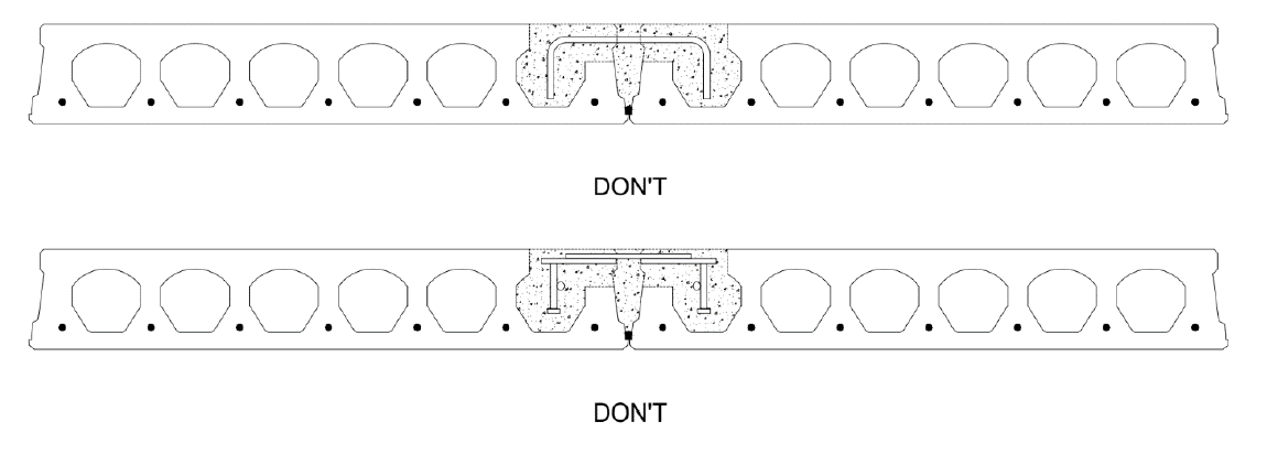
The point of this exercise is to demonstrate that a nominal amount of reinforcing at each end of the NiCore™ Plank can provide sufficient clamping action and ductility for shear friction. Considering the typical reinforcing used to satisfy minimal structural integrity requirements prescribed by the International Building Code, it should very rarely be needed to add additional shear friction reinforcement or even introduce the connections shown below. Wet connections with rebar staples or dry connections with embedment plates with welds add considerable premium to the costs of producing and erecting NiCore™ Plank and are to be avoided at all cost.
We trust this narrative is helpful in explaining how longitudinal grout joints are constructed and designed, but if we can be of further assistance, do not hesitate to contact us as indicated below.
Nitterhouse Concrete Products, Inc. in Chambersburg, PA, is a family-owned company serving the construction industry since 1923. Give us a call at 717-267-4505 or visit our website at www.nitterhouse.com for information on more quality precast, prestressed products to meet your design and construction needs. Choose with confidence and make NCP as your single source for precast – what you need when you need it.
Contact Nitterhouse Concrete Today