Lateral seismic and wind loads significantly influence the selection of structural framing for precast parking structures. While it is not always the case, seismic loading usually controls the lateral design because it is a direct function of the mass of the structure, and robust precast concrete structures are naturally more massive than many other building materials. The primary methods of resisting lateral loads in structures are “X” braces, moment frames, and shear walls. Shear walls are a very efficient solution for minimizing lateral drift and are commonly used in precast parking structures to resist lateral seismic and wind loads.
This narrative is intended to assist architects and engineers by addressing important structural and construction considerations related to the design of the shear wall panels. For further information on a “high altitude” perspective of how the architectural and structural selection of precast framing affects other important functional and serviceability aspects of the parking structure, the reader is directed to a companion document entitled Seismic & Wind Loading For Parking Structures – Shear Walls & Openness.
Observations for Shear Wall Design
Before looking at some examples, here are some very basic observations to keep in mind…
- Designing structures for lateral seismic loads is a delicate choreographing of providing sufficient stiffness to limit the lateral drift of the structure while controlling the magnitude of lateral forces and maintaining ductility. Perhaps a more intuitive description is that in contrast with lighter, more flexible steel structures, the mass of concrete shear wall structures will attract higher lateral seismic forces, but their robust stiffness results in significantly less lateral drift. Steel structures desire greater stiffness to limit lateral drift, while concrete structures desire greater flexibility to limit lateral forces.
- The most efficient shear walls capture as much dead load as possible to counter the effects of overturning moments. The advantage of this will be evident in following examples.
- Simply making shear walls longer to reduce or eliminate uplift forces will have the undesirable effect of overly stiffening the structure and increasing the lateral seismic load. This, in turn, requires longer shear walls, resulting in higher lateral seismic loads – analogous to a dog chasing its own tail.
- As noted in the previously mentioned companion document, making the shear walls longer reduces the openness of the perimeter of the structure, and could possibly result in the need for mechanical ventilation throughout the service life of the structure.
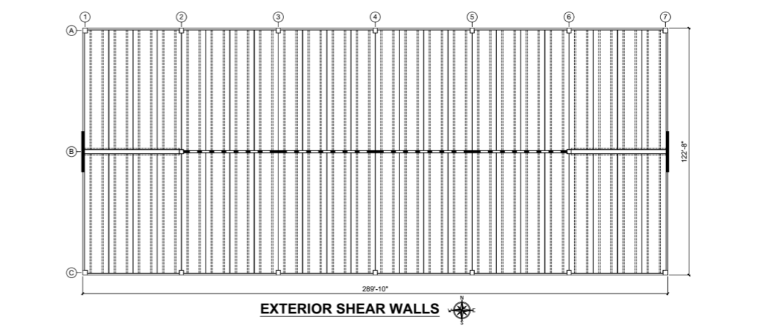
- It is desirable to avoid placing shear walls near the building corners. While it is tempting to try and utilize stair / elevator towers for lateral load resistance, this can prove to be more of a liability than an asset. This is because the towers are typically located at the “dead zones” at the extreme corners of the structure where the cumulative result of volumetric movement due to temperature, shrinkage, etc. is most pronounced. Adding stiff structural elements to resist lateral loads at these locations might be more problematic than beneficial. The arrangement of shear walls shown in the floor plan below is less vulnerable to attracting volumetric forces (Note: Stair / elevator towers are not shown for clarity).
- Unlike wind loads, the magnitude of which is determined by the structure’s exterior wall surface area, the magnitude of seismic loads is determined by the structure’s mass. In the floor plan shown below, the wind loads in the north/south direction are about 289.83’ / 122.67’ = 2.36 times larger than those of the east/west direction. By simple inference, the shear walls resisting wind in the north/south direction need to be about 2.36 times stiffer than those of the east/west direction. This is not the case, however, for the seismic loads. Because the mass of the structure remains constant the lateral seismic demand is nearly the same for both orthogonal directions. A 5% minimum prescribed load eccentricity, or the actual eccentricity of the structures mass, will increase these seismic demand forces, but the basic concept remains the same.
Examples of Shear Wall Design Considerations in Parking Structures
In the examples that follow, we will assume a parking structure located in Philadelphia, PA. The scope of this narrative is limited to very general concepts and is not intended to be an exhaustive presentation of seismic design methodology. Nonetheless, the following seismic design parameters were used to arrive at the order-of-magnitude of the forces shown.
Risk Category: II
Seismic Importance Factor (Ie): 1.0
Site Classification: D
Ss = 0.180 Fa = 1.600 SMS = 0.288 SDS = 0.192
S1 = 0.047 Fv = 2.400 SM1 = 0.113 SD1 = 0.075
Seismic Design Category (SDC): B
Basic Structural System: Bearing Wall System
Seismic Resisting System: Intermediate Precast Shear Walls
R = 4 Ω0 = 2.0 Cd = 4.0 TL = 6 Seconds
Assumed structure dead load = 130 psf per level
Assumed shear wall thickness = 14″
First story = 11’-8” Typical story = 10’-6”
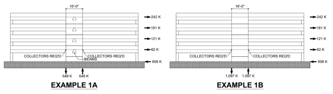
In Example 1A shown above the minimum length of the shear wall stack is 16’-0” and it supports gravity loading from the precast beams behind. Collectors will likely be required at each end to fully capture the diaphragm shear, and the approximate tensile and compressive forces are 648 K (i.e.: the equivalent of twelve #9 bars). To show the effect when no gravity loading is present except the weight of the shear walls themselves, no precast beams are shown in Example 1B. A 16’-0” shear wall stack can still resist the lateral loads, but the approximate tensile and compressive forces increase to about 1,097 K (i.e.: the equivalent of sixteen #10 bars). This is a 69% increase just because the dead load has been eliminated!
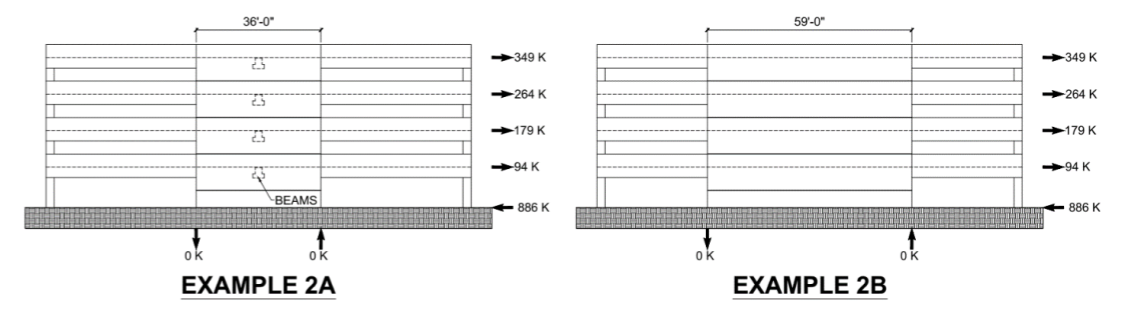
In Example 2A shown above the shear wall stack is lengthened to 36’-0” to eliminate uplift forces. The base shear has increased from 606 K in Examples 1A and 1B to 886 K because the stiffness of the structure has increased considerably. While this might not appear to be significant a 36’-0” shear wall when compared with a 16’-0” shear wall is (36.0)³ / (16.0)³ = 11.4 times stiffer. Example 2A takes advantage of additional gravity loading from the precast beams behind, but Example 2B shows how elimination of this additional dead load requires the shear wall stack to increase from 36’-0” long to 59’- 0” long to eliminate uplift forces.
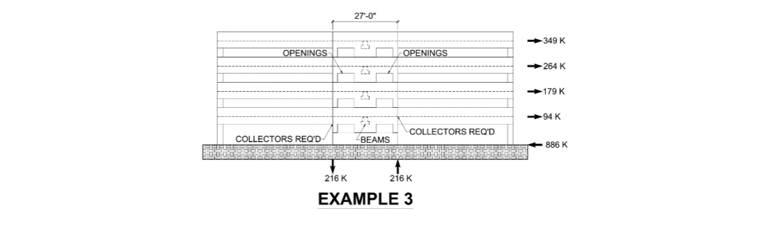
Another option to consider is depicted in Example 3 shown above. This is a compromise to reduce the uplift forces while providing for more openness on the exterior of the structure. The ends of the shear wall contain the tensile reinforcement while the middle behaves as a discrete “column section” to support the gravity loads from the beams behind. It is beyond the scope of this narrative to address all the structural design requirements, but it is needful to resolve all the vertical and horizontal shear, tensile, and compressive forces through the net concrete section.
As simplistic as these examples may appear, they help to depict the ramifications of the shear wall design selection. But that is just the “tip of the iceberg”, because the shear wall selection directly affects the foundation selection because of the method by which the overturning moments are being addressed by the shear walls. As we have already seen, shear walls of relatively short length as in Examples 1A and 1B can resist the lateral loads, but they will result in significant uplift forces at the leeward end that need to be held down by the foundation. Or, the shear walls can be lengthened to lower or eliminate the uplift forces, thus reducing the uplift forces on the foundation, as depicted in Examples 2A and 2B. In approximate terms, the choice is between putting more mass above grade in the precast shear walls, or below grade in the cast-in-place foundations.
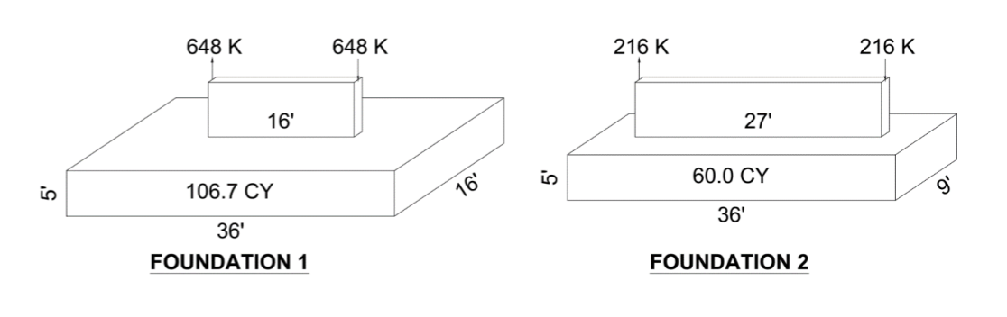
For purposes of illustration, Foundation 1 shown below supports the overturning reactions from Example 1A above. When designing foundations, the International Building Code (IBC) permits a 25% reduction in load intensity. Accordingly, the net overturning moment = (0.75)(648 K)(16’) = 7,776 ‘K. For the foundation shown, the resisting dead load moment = (106.7 cy)(27 cf / 1 cy)(0.150 K / 1 cf)(18’) = 7,778 ‘K. Similarly, Foundation 2 shown below supports the overturning reactions from Example 3 above. In this case, the net overturning moment = (0.75)(216 K)(27’) = 4,374 ‘K. For the foundation shown, the resisting dead load moment = (60.0 cy)(27 cf / 1 cy)(0.150 K / 1 cf)(18’) = 4,374 ‘K.
These are sizeable foundations, not only for resisting lateral wind and seismic loads, but also for resisting gravity loads. Neglecting live load reduction and combinations of loads the order of magnitude reaction of gravity loading (including the foundation weight) that Foundation 1 needs to support is about 1,586 K, and Foundation 2 needs to support about 1,469 K. Under gravity loads alone the soil bearing stress for Foundation 1 is about (1,586,000 #) / (36’)(16’) = 2,753 psf, and the soil bearing stress for Foundation 2 is about (1,469,000 #) / (36’)(9’) = 4,534 psf. And this is only a five-story structure!
In the event the geometry of the structure, number of stories, site conditions, proximity to other structures, etc. preclude the use of broad, shallow foundations such as these then deep foundations need to be utilized. This usually permits a smaller footprint for the pile cap but will undoubtedly result in uplift forces that rely upon tension piles to resist the uplift forces through the action of shaft friction along their length, engagement of helical bearing plates, or by bonding the piles into rock.
Contact Nitterhouse Masonry for Precast Concrete Products
Nitterhouse Concrete Products, Inc. in Chambersburg, PA, is a family-owned company serving the construction industry since 1923. Give us a call at 717-267-4505 or visit our website at www.nitterhouseconcrete.com for information on more quality precast, prestressed products to meet your design and construction needs. Choose with confidence and make NCP your single source for precast – what you need when you need it.
Contact Nitterhouse Concrete Today